Converting a printer made of plastic into a Bioprinter
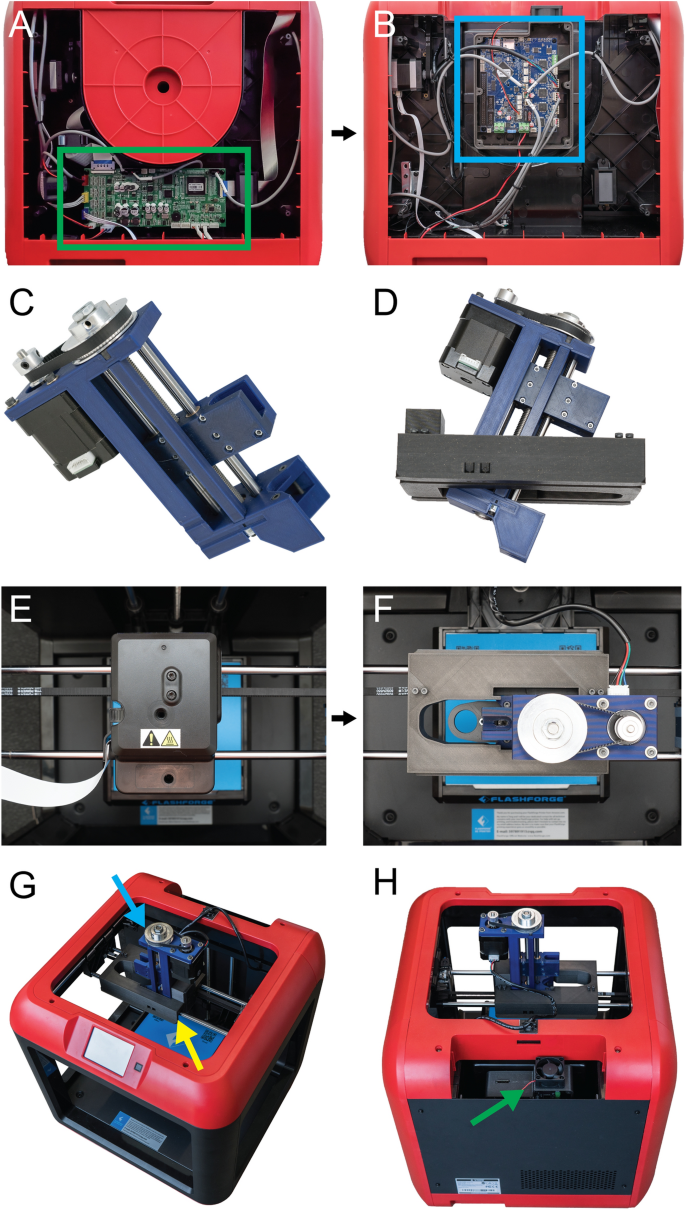
[****]There are several steps involved in converting a 3D printer made of plastic into a bioprinter. These steps generally follow the same sequence (Fig. 1). First, the electronic and control systems of the plastic printer need to either be modified or replaced. The FlashForge Finder motion controller circuit board (Fig. 2A, the green rectangle) has been replaced by the open-source Duet 2 WIFI motion control circuit board (Fig. 2B, blue rectangle). This is done to increase the motion control performance, enable WiFi access, and facilitate quick firmware customization via the Duet web-based interface. This process is described for FlashForge Finder. It can be adapted for other desktop 3D printers by following the supplemental assembly guide and Supplementary Figs. S1–S15, and provided Duet2 WiFi configuration files). Next, we replace the thermoplastic extruder with the Replistruder 4 an open-source high-performance syringe extruder. This extruder is a modified version of the Replistruder 3.14. Replistruder 4’s majority of parts can be 3D printed of plastic and assembled with common hardware (Fig. 2C). The carriage platform was created to mount the Replistruder on existing linear motion components. The X-axis carriage includes pockets for bearings that are already mounted on the linear rails of the X, as well as channels to route and retain the Xaxis belt. Four mounting points are provided with M3 hex nuts that can be recessed to attach the Replistruder 4 (Fig. 2D). The thermoplastic printhead that comes pre-installed on the Finder is replaced with the X-axis carriage/Replistruder 4 assembly (Fig. 2E,F. Details in the Supplementary Assembly Guide and Supplementary Figures. S16–S23). After these steps are complete, the Replistruder 4(Fig. 2G, blue Arrow) is mounted in the X axis carriage of the printer (Fig. 2G yellow an arrow) and the motors are connected with the Duet 2 WIFI, which can be found in the back of the bioprinter. 2H, green arrow). The FlashForge Finder can be transformed with these modifications into an open source bioprinter equipped with a motion control system and a high performance extruder.


[****]Duet 2 WiFi offers several key advantages over stock motion control circuit boards in the FlashForge Finder or other low-cost desktop 3D printing machines. First, the Duet’s WiFi based web interface allows for easy, in-browser access to printer movement, file storage and transfer, configuration settings, and firmware updates. This is in contrast with most 3D printers where editing configuration settings requires flashing motion control board firmware via 3rd-party software. Inexperienced users may find this daunting and difficult. This could result in accidental firmware changes and corruption. Second, the Duet 2 adds many advanced motion control improvements including (i) a 32-bit electronic controller, (ii) high performance Trinamic TMC2260 stepper controllers, (iii) improved motion control with up to 256 × microstepping for 5 axes, (iv) high motor current output of 2.8 A to generate higher power, (v) an onboard microSD card reader for firmware storage and file transfer, and (vi) expansion boards adding compatibility for 5 additional axes, servo controllers, extruder heaters, up to 16 extra I/O connections, and support for a Raspberry Pi single board computer. The Duet 2 WiFi setup guide and support documentation are comprehensive, up-to-date, and supported by an active forum. The Duet2 WiFi setup guide and the hardware details are provided. However, the official Duet3D documentation can be accessed for those who wish to modify the Duet2 WiFi. These features combine to provide precise motion control, extensive expandability, and a web interface that allows for rapid customization and better performance than standard desktop plastic printers.
3D Bioprinter Mechanical Performance
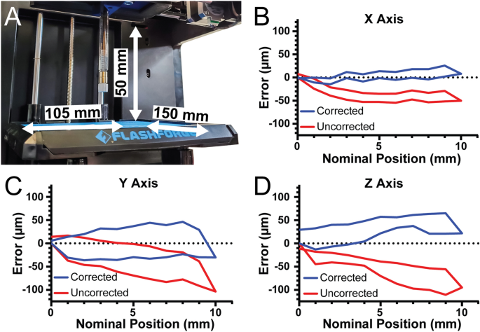
[****]To determine the 3D bioprinter’s build volume, the X-, Y-, and Z axis travel limits were determined after conversion. For the X-axis travel is 105 mm, for the Y-axis travel is 150 mm, and for the Z-axis travel is 50 mm, resulting in an overall build volume of 787.5 cm3 (Fig. 3A). Stepper motor driven motion systems, such as this 3D Bioprinter and most commercial 3D Printers, have one parameter that is crucial to their performance. This parameter is the steps per.mm calibration of each axes. This number is used to determine how many pulses (or steps) must be sent to each stepper motor to move each axis precisely one millimeter. This formula is for the belt-driven X and Yaxes. (steps/mm=(steps/rotationtimes microsteps)/(belt pitchtimes pully teeth)). For the Finder these parameters are the nominal pitch of the driving belt (2 mm), the number of teeth in the motor’s pully (17 teeth), the number of steps in a full rotation for the motor (200 steps), and the number of microsteps that the Duet 2 WiFi interpolates between the full steps (set to 64 microsteps). In this example, the nominal steps/mm are 376.5 for the X-axis and Y axes. The formula for the Z-axis is (steps/mm=(steps/rotationtimes microsteps)/(screw pitchtimes screw starts)). The finder uses a 4 start, 2 mm pitch lead screw so the nominal steps/mm for 16 × microstepping is 400 steps/mm.

[****]There are many key specifications that can be used to compare 3D bioprinter performance. They all relate to print quality. The majority of thermoplastic 3D printers have specifications for resolution. This is the smallest possible step that the printer can take in any direction. Table 1 lists the reported numbers for both the FlashForge Finder as well as several commercially-available bioprinters. Additional specifications regarding the motion system include positional errors, which are the absolute deviation of current location of the printer from its intended location, as well as repeatability, which refers to the maximum absolute deviation from the average measured position for multiple attempts to reach that position. These advanced metrics are often not available in the bioprinting industry and can differ between printers due to differences in mechanical components and assembly accuracy. Bioprinter specifications generally provide ideal resolution based on the nominal dimensions of the pulleys, gears and screws that are used to assemble the motion systems. None of the manufacturers mentioned above provide actual resolution measurements. This means that there is no error across the entire distance of travel or repeatability. These measurements are often provided by ultra-high-end motion platforms like those offered by Aerotech and Physik Instrumente.28,29. Measure the travel distance with an external tool to optimize these low-cost 3D printers.
[****]To verify that the nominal steps/mm values were correct, we quantified positional error of our system along each axis near the center of travel with 2 µm precision. The nominal steps/mm values showed a systematic undertravel for the X-axis (Fig. 3B, red curve. Using the maximum error at 10 mm of travel we determined the number of missed steps per mm and corrected the value, and with this corrected steps/mm the average travel error over the 10 mm window was 7.9 µm (Fig. 3B, blue line. Systematic under-travel was observed on the Y-axis using the nominal steps/mm. (Fig. 3C, red curve) and after correction this was reduced to 29.1 µm (Fig. 3C, blue curve. Finaly, the Z-axis was subject to systematic under-travel according to the nominal steps/mm (Fig. 3D, red curve) and after correction was reduced to 32.3 µm (Fig. 3D, blue curve. The values also enable calculation of the unidirectional repeatability, which is the accuracy of returning to a specific position from only one side of the axis (e.g., from 0 to 5 mm) and the bidirectional repeatability, which is the accuracy of returning to a specific position from both sides of the axis (e.g., from 0 to 5 mm and from 10 to 5 mm). For the X-axis, the unidirectional repeatability was 3.9 µm, and the bidirectional repeatability was 16.4 µm. For the Y-axis, the unidirectional repeatability was 11.5 µm, and the bidirectional repeatability was 63.9 µm. For the Z-axis, the unidirectional repeatability was 8.7 µm, and the bidirectional repeatability was 38.7 µm. Together these measurements demonstrate that with calibration the travel of our converted bioprinter had a maximal error of 35 µm and repeatability in worst case situations of 65 µm. Whereas before calibration there was a linearly increasing error in position, after calibration this error is significantly decreased. This calibration, or at the very least the measurement of errors, is essential to determine whether flaws in printed structures are caused by the printer or other factors.
Bioprinter printing fidelity:
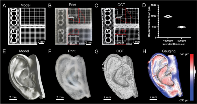
[****]Fidelity and resolution of printed constructs are typically not quantified for 3D bioprinters because they cannot print bioinks in a manner approaching the mechanical limitations of the systems. However, advances in embedded bioprinting techniques like FRESH have allowed for some remarkable improvements.13, it is now possible to perform extrusion bioprinting with resolutions approaching 20 µm. Thus, to demonstrate bioprinter printing performance we generated a square-lattice scaffold design consisting of 1000 and 500 µm filament spacing (Fig. 4A) To measure the accuracy of FRESH printing using a collagen type 1 bioink (Fig. 4B). 3D volumetric images were taken using optical coherence imaging (OCT) to measure grid spacing (Fig. 4C)30The results showed a close match between the measured and as-designed dimensions (Fig. 4D). Following this was a more complex design, based upon a 3D scan (Fig. 4E). This model was printed with collagen (Fig. 4F). We used OCT to capture a 3D volumetric image (Fig. 4G, SupplementaryFig. S24)30. The 3D reconstruction demonstrates recapitulation of the features of the model and 3D gauging analysis revealed a deviation of − 29 ± 107 µm (mean ± STD) between the FRESH printed ear and the original 3D model (Fig. 4H)30. These two examples show that the standard deviation and average error of printed scaffolds is within the limitations of the bioprinter built and are comparable to commercial bioprinters.31.
