Multilayer Halbach magnet
The Multilayer Halbach Magnet (MLHM) developed on this research is a three-layer cylindrical magnet with a nested, rotatable interior layer (Halbach array) for mechanical shimming (Fig. 3a). The design of the rotatable mechanical shimming layer was carried out utilizing 3D CAD and finalized utilizing a high-resolution 3D printer (FelixPrinter FFF 3D Printer). Sintered magnet parts of Neodymium-Iron-Boron (NdFeB) grade N42 have been bought (Ningbo Everlasting Magnetic Supplies Ltd.-NGYC, Yinxian Ningbo). The person magnets are nickel-coated cubes with facet dimensions of (20, 10, 6, ; mathrm{and} ;;3; mathrm{mm}) (pm 0.05 ; mathrm{mm}). The remanence is ({B}_{R}=1350; mathrm{mT}), coercivity ({H}_{c}=923 ; {textual content{kA}}/textual content{m}) and most power product ({(BH)}_{max}=318.3; mathrm{KJ}/{mathrm{m}}^{3}, =42 ; mathrm{MGOe}). Moreover, the finished Halbach array features a quadrupole layer comprising 4 ferromagnetic cubes, every with a facet dimension of 40 mm, fabricated from ferromagnetic metal and coated with nickel. This quadrupole layer is designed to govern magnetic subject strains, concentrating and bending them to strengthen the magnetic subject and decrease magnetic stray fields29 (Fig. 3b). The focusers are merely an method to design an anti-bend magnet primarily based on a quadrupole30. The focusers, within the type of triangular cavities with a 20 mm base and three mm peak, are oriented as proven in Fig. 3a and crammed with iron powder to reinforce the magnetic subject on the candy spot. The association of magnetic parts in every layer follows a cubic void alignment primarily based on Eq. (3) and is illustrated in Fig. 3a.
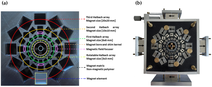
(a) Multilayer Halbach magnet designed utilizing 3D CAD and finalized with a 3D printer. Three layers, rotatable elements, magnetic focusers, and magnet parts are color-coded for readability. (b) The absolutely assembled Halbach magnet contains the mechanical and electrical shimming elements, together with the shimming kernel.
To facilitate mechanical shimming, the finished magnet was enclosed with a 5 mm thick aluminum body, permitting the mounting of a micrometer screw. The magnetic subject energy on the nominal candy spot throughout the magnet bore was fine-tuned by inserting an ultrafine polished ferromagnetic cylinder fabricated from ferritic metal. This cylinder serves as a filler to normalize the stray magnetic subject strains and cut back the magnetic subject energy, enabling operation at decrease frequencies31,32.
({{{B}}}_{0}) mapping
Absolutely the ({B}_{0}) subject energy of the MLHM magnet, earlier than equipping it with the shim system, was mapped by putting a directional magnetometer (gaussmeter) contained in the magnet bore, aligned parallel to the (z{textual content{-}}mathrm{axis}). Exact positioning of the magnetometer was achieved utilizing a high-precision 3-axis stage micrometer (Thorlabs, Inc.). The ({B}_{0}) mapping course of encompassed the complete usable quantity (D = 6 mm, L = 6 mm) (indicated by the purple circles in Fig. 4). Moreover, ({B}_{0}) mapping was carried out at three particular slices positioned at − 1.5 mm, 0 mm, and 1.5 mm throughout the confined quantity later occupied by the solenoid coil (marked by inexperienced circles). The mapping initiated from the nominal candy spot of the magnet and systematically moved to cowl 250 knowledge factors throughout the (z{textual content{-}}y) aircraft for every of the amount slices. These measurements have been carried out by inserting a magnetometer connected to a 3-axis stage micrometer into the magnet bore. Absolutely the mapping, carried out previous to inserting the shim system, gives precious insights into the general subject inhomogeneity of the magnet. This data is essential for figuring out a shim-usable quantity, which corresponds to the vary {of electrical} shimming capabilities. The distribution of magnetic subject strengths, calculated from the measured knowledge factors, is represented within the density plot proven in Fig. 4a–f. These plotted factors cowl the (z{textual content{-}}y) aircraft at (x = -1.5) mm, 0 mm, and 1.5 mm.
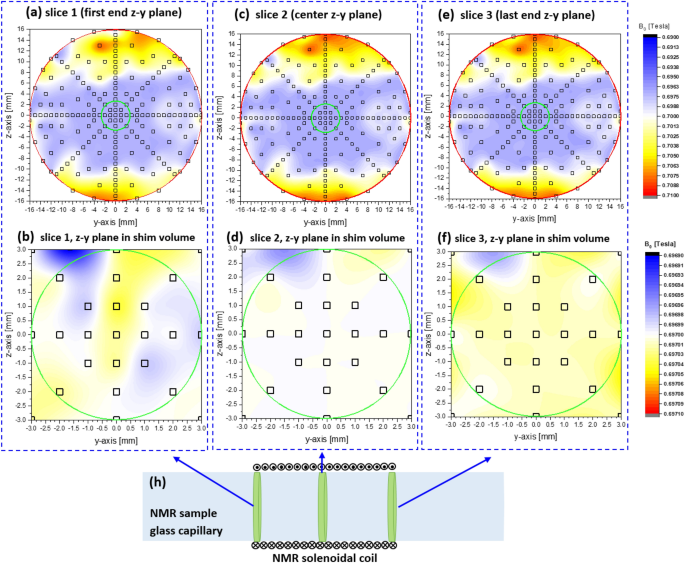
Absolute ({B}_{0}) mapping was carried out within the 3.4 mm bore of the MLHM magnet with out working the shim system (inexperienced circle represents the entire quantity). The mapping encompassed three quantity slices throughout the (z{textual content{-}}y) aircraft, comparable to the 2 ends and the middle slices (a, b, and c). Subsequently, (d, e, and f) illustrate absolutely the ({B}_{0}) mapping of the usable cylindrical cavity (D = 6 mm, L = 6 mm) (inexperienced circles characterize the shim-usable quantity) after the shim system was inserted. (h) Depicts the glass capillary (2.4 mm ID and three mm OD) containing the NMR solenoidal coil the place the NMR pattern is positioned, exhibiting the three (y{textual content{-}}z) slices throughout the shim quantity.
The shim course of aimed to rectify the magnetic subject inhomogeneities throughout the accessible cylindrical cavity of the MLHM magnet ((mathrm{D}=6) mm, (mathrm{L}=6) mm, as denoted by the interior inexperienced circles in Fig. 4) by using a mixed mechanical and electrical method (confer with “Mechanical shim system” and “Electrical shim system” sections). The efficient shim was utilized to the amount fraction occupied by the pattern throughout the solenoidal coil, which was roughly 3 mm in size and had a 3 mm interior diameter (ID). Nevertheless, the complete cylindrical cavity ((mathrm{D}=6) mm, (mathrm{L}=6) mm) was shimmable. The probehead’s positioning capabilities throughout the (y{textual content{-}}z) aircraft had a variety of 1.2 mm, which proved fully satisfactory for figuring out essentially the most homogeneous quantity to embody the pattern, thereby reaching the narrowest line width and optimum sign form.
Mechanical shim system
A rotatable home made magnetic layer, configured within the Halbach kind (Fig. 5), was put in because the preliminary layer of the MLHM magnet (highlighted in yellowish-green and labeled in Fig. 3) to vary the orientation of the magnetic subject vector throughout the (z{textual content{-}}y) aircraft.
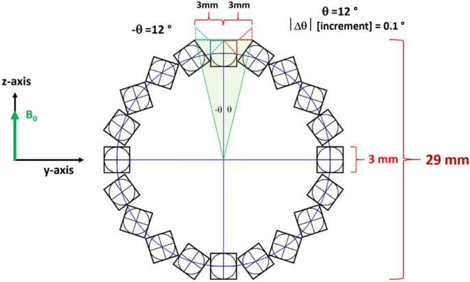
The rotatable Halbach layer served as an built-in mechanical shim system for adjusting ({B}_{z(z{textual content{-}}y ;aircraft)}) by means of a restricted rotation throughout the (z{textual content{-}}y) aircraft starting from (-12^circ) to (+12^circ).
The rotatable shim layer is secured to a custom-made spring-loaded micrometer, enabling a reversible and exact rotational adjustment of 1⁄120 of the cubic ingredient’s dimension throughout the shim ring (3 mm). The mechanical shimming system contributes to the magnetic elements of ({B}_{z(mechanical)}) and enhances the ({B}_{z})-component of ({B}_{0}). To attain larger ({B}_{z}) homogeneity, positive shimming is important in (mathrm{X},mathrm{ Y},mathrm{ Z},mathrm{ ZX},mathrm{ ZY},mathrm{ XY ;; and } ; ;{mathrm{Z}}^{2}) channels. Due to this fact, we integrated {an electrical} shim system to fulfill these necessities.
Electrical shim system
The wide-bore magnet was designed to accommodate {the electrical} shimming system, as proven in Fig. 6. This 7-channel shim system features a shim kernel in a Helmholtz configuration, which helps the usual gradient shim coil design. {The electrical} part of the shim kernel is related to a programmable homebuilt digital 7-channel present supply, able to offering as much as (pm 2 ;mathrm{ A}) per channel with a decision of 0.05 A. To suit throughout the slim bore of the Halbach magnet used on this work, some shimming channels and better orders have been omitted. As an alternative, we changed the sometimes used versatile printed circuit board (PCB, FR-4) with copper shim coils wound on hole tubes, built-in as a part of the shim kernel, as depicted in Fig. 6. The design of the shim kernel was created utilizing 3D CAD and was finalized by using a 3D printer (Dremel DigiLab 3D45 3D Printer). Within the authentic shim system, the addressed shim coils included X, Y, Z, XY, XZ, YZ, X2 − Y2, and 2Z2 − X2 − Y2 shim coils. Nevertheless, on this work, we targeted on Z2, X, Y, Z, XY, XZ and YZ shims primarily based on the 3D configuration. This selection was made for (i) These axes are essentially the most influential in reaching a uniform magnetic subject on the candy spot. (ii) The accessible area throughout the extraordinarily small cavity wanted to accommodate the pattern, shim kernels, wires, and passive warmth dissipation. (iii) Increased-order harmonic shims would have required lithographic patterns on a PCB, which couldn’t be mounted throughout the shim kernel. Due to this fact, we chosen the upper order of Z2, which might be managed with 5 copper wires in an elliptical kind connecting all channels, forming the second order as described within the literature33. For different channels, we established a reference with the X shim coil axis. Subsequently, the X shim coil, which rotates 90° across the z-axis, was designated because the Y shim coil, with the z-axis fastened within the path of the Halbach magnet’s ({B}_{0}). The XZ shim coil rotates by 45° across the Y-axis, and correspondingly, the XZ shim coil that rotates 45° across the z-axis was labeled because the YZ shim coil34,35. The copper shimming coils have been coated with three layers. First, a layer of zirconia, a superb electrical insulator with excessive thermal conductivity (thermal conductivity of 8.1 W/m Ok36) was utilized to offer each electrical insulation and mechanical safety for the coils. Second, an epoxy layer was added on prime of the zirconia on account of its excessive warmth conduction and low warmth capability. Lastly, a silver-based resin was utilized to reinforce thermal conductivity, facilitating larger passive warmth dissipation. These three layers have been coated with thicknesses starting from 200 to 500 μm to forestall thermal storage that would result in temperature overshoot.
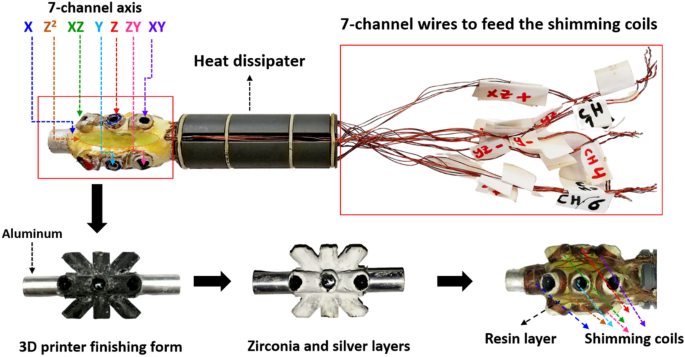
The shimming kernel that includes 7-Helmholtz axis coils, designed utilizing 3D CAD and produced by means of 3D printing. Every axis’s coils are divided into 4 parallel paths to attenuate ohmic heating.
Passive warmth dissipation and switch utilizing the shim kernel have been adopted on this research, together with its extension past the magnet cavity. Energy dissipation is immediately associated to the whole mass of the dissipater. The shim kernel has a quantity of roughly 55 55 cm3 and a mass of roughly 18 g, with an efficient floor space, together with the inner elements, of 105 cm2. To handle the Joule heating generated by the shim system, particularly when working the shimming present at most ranges ((pm 2 ; mathrm{ A}) for every channel), every shim coil per channel was break up into 4 coils related in parallel to scale back electrical resistance. Consequently, the operating electrical currents have been diminished to 1 / 4 of the primary channel present, leading to a fourfold discount in dissipated warmth (({mathrm{E}}_{dis}={mathrm{I}}^{2}mathrm{R}), the place (mathrm{I}=) electrical present, and (mathrm{R}=) Ohmic resistance) on the pattern spot. This discount led to a lower in temperature from 96.2 to 32.6 °C at full operation currents (14 A for all channels). Whereas thick copper wires can cut back Joule heating, it is necessary to notice that the magnetic subject energy of a coil is expounded to the ampere-turns of the coil. Extra turns end in a larger induced magnetic subject energy. Thick copper wires might restrict the flexibility to satisfy this situation, particularly within the restricted size (roughly 5 mm) of the levels throughout the shim kernel. In conclusion, by implementing the 2 modifications, {the electrical} shim system was capable of function at typical shim currents of round 0.1 A per channel with out inflicting a big enhance in pattern temperature (roughly (0.1 ; ^circ mathrm{C})), as illustrated in Fig. 7 (blue knowledge factors). Whereas working the 7-axes shimming coils at most present is uncommon, testing underneath excessive circumstances concerned working all shim channels at half of the utmost and full most currents (1 A and (2;mathrm{ A}), respectively) for validation functions. Below these circumstances, the shim-kernel system exhibited stability, with temperature will increase above room temperature measured at (0.3;^circ mathrm{C}), (3.0;^circ mathrm{C}), and (5.0;^circ mathrm{C}) for currents of (0.1) (mathrm{A}), (1mathrm{ A}), and (2mathrm{ A}), respectively.
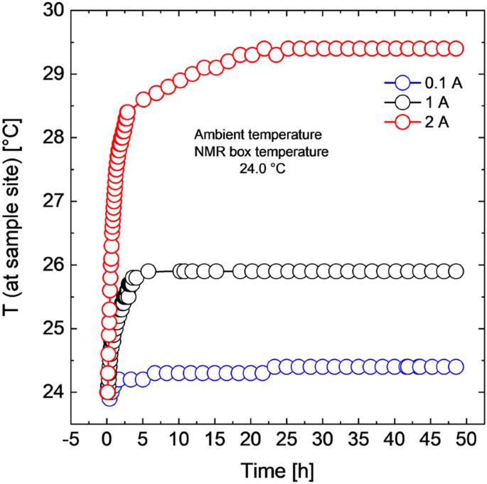
Temperature modifications on the pattern web site throughout operation of {the electrical} shim system at currents of 0.1 A, 1.0 A, and a pair of.0 A per shim channel, illustrating the effectiveness of warmth dissipation from the pattern web site.
Planar NMR probehead
An NMR probe (Fig. 8a) was constructed on a printed circuit board fabricated from glass-reinforced epoxy laminate (RT4) with a double copper layer, every with a thickness of 35 µm37. The structure of the resonance circuit and the r.f. BNC copper tracks have been created on the NMR probehead board utilizing UV lithography. The NMR resonator is a solenoidal coil with a copper wire diameter (D) of 200 µm, consisting of 11 turns wound round a high-resolution NMR glass tube with an outer diameter (OD) of three mm and an interior diameter (ID) of two.4 mm. The solenoidal coil accounts for the key a part of the inductance (roughly 0.70 μH), whereas the onboard copper monitor connectors contribute about 0.15 μH to the resonance circuit (Fig. 8b). Bonding wires and connection factors introduce impedance discontinuities, resulting in elevated transmission loss and sign reflection38, significantly as resonance frequency will increase39, even at low-field NMR. Due to this fact, the NMR probe was designed as a solenoidal mini coil built-in right into a planar design to reinforce sensitivity, decrease B1 inhomogeneity, and cut back the affect of bonding wires and connection factors on impedance discontinuity and sign transmission loss. Nonmagnetic trim multi-turn and ceramic chip capacitors (Voltronics Corp., Salisbury, MD, USA) have been used to tune and match the resonance circuit to 29.934 MHz. The nutation spectrum (Fig. 8c) for the mounted solenoid mini-coil within the probe-head demonstrates the energy and homogeneity of the r.f. subject. On this case, the sign depth as a perform of pulse size reveals a robust r.f. subject at an influence of solely 2 W. Pattern temperature was detected utilizing a Pt100 sensor positioned close to the pattern. Temperature calibration on the candy spot was achieved primarily based on the chemical shift variations of ethylglycol40. {The electrical} circuit of the NMR probe-head, together with matching and tuning capacitors, is proven in Fig. 8b. The probe-head efficiently achieved a tough pulse size of 1.55 μs at 2 W.
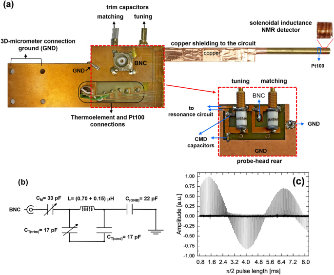
(a) Solenoidal-based NMR resonator (probehead) together with on-chip thermal parts, a BNC r.f. connector, and electrical connections. (b) {The electrical} circuit of the NMR probehead tuned and matched at 29.934 MHz, exhibiting the tuning and matching capacitors and the ohmic resistance of the circuit. The coil consists of 11 turns, with a 3.4 mm OD, 3 mm ID, and an inductance of roughly 0.70 µH, utilizing a copper wire with a diameter (D) of 0.2 mm. The inductance of the onboard copper strip line connectors is roughly 0.15 µH. (c) The nutation curve obtained with the probehead in (a).
The sensitivity of the homebuilt planar NMR probe, within the NMR experiment at a magnetic subject energy of 0.703 T (29.934 MHz for 1H), is set utilizing the signal-to-noise ratio (SNR), sometimes outlined because the ratio of the peak of a resonance of curiosity to twice the root-mean-square of the noise stage. On this research, the SNR of the anomeric proton of sucrose was measured to quantify the sensitivity of the planar NMR probe, following a typical protocol within the literature41. The sucrose pattern had a quantity of roughly 35 µL at a focus of 21.8 mM in ({mathrm{D}}_{2}mathrm{O}), however the SNR is immediately proportional to the amount fraction occupied by the pattern throughout the coil, making the efficient pattern quantity round 14 µL. With an experiment time of 8 accumulation scans, every taking 1.9 s per scan, and an SNR of 116, the restrict of detection (({nmathrm{LOD}}_{m})) is calculated utilizing the method ({nmathrm{LOD}}_{m}=79 ; textual content{nmols}^{1/2}) at 29.934 MHz calculated from the method ({nmathrm{LOD}}_{m}=3nsqrt{{t}_{exp}}/mathrm{SNR ;;the place} ;; n) [mol] refers back to the portion of the pattern throughout the 14 µL detection quantity, and ({t}_{exp}) is the whole experiment time (accrued over 8 scans). To check this measurement to at least one carried out at an NMR frequency of 600.13 MHz, the consequence was normalized by multiplying it by an element of 189, following the scaling relationship ({left[{upomega }_{L}right]}^{7/4})42,43. The LOD falls throughout the vary of 15–30 mg/L.
Water indicators have been obtained utilizing the onboard NMR probe inside a 3.0 mm OD and a pair of.4 mm ID NMR glass tube, with a size of three mm, as proven in Fig. 9. The black spectrum represents knowledge acquired with none shimming system, leading to a linewidth of 11 Hz and a non-pure Lorentzian spectral line form as a result of affect of ({mathrm{B}}_{0}) magnetic subject inhomogeneity. In distinction, the blue spectrum, acquired with mechanical shimming alone (no electrical shimming), demonstrates noticeable enhancements, with a diminished linewidth of roughly 8.0 Hz and a principally Lorentzian form. The purple spectrum, acquired with each mechanical and electrical shimming, reveals an additional discount in linewidth to five.5 Hz and a purely Lorentzian sign form, indicating considerably enhanced homogeneity of the ({mathrm{B}}_{0}) magnetic subject.
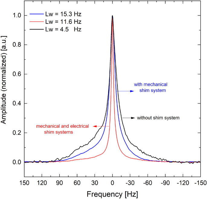
Water indicators acquired with out a shimming system (black), with mechanical shimming (blue), and with mixed mechanical and electrical shimming (purple).
Low-field NMR spectrometer
The homebuilt LF-NMR spectrometer (Fig. 10) is supplied with an MLHB magnet working at 29.934 MHz and is related to the Pulse Blaster interpreter (SpinCore Applied sciences, Inc., Gainesville, FL, USA) for instrument management. The magnetic subject energy of the MLHB magnet might be adjusted throughout the vary of 0.5–0.77 T primarily based on the thickness of the ferromagnetic cylindrical filler within the magnet’s cavity (as defined in “Multilayer Halbach magnet” part). Consequently, the spectrometer can function at frequencies starting from 21.25 to 32.78 MHz for protons, requiring acceptable tuning and matching of the NMR probehead. The Pulse Blaster interpreter (SpinCore Applied sciences, Inc., Gainesville, FL, USA) was utilized for instrument management.
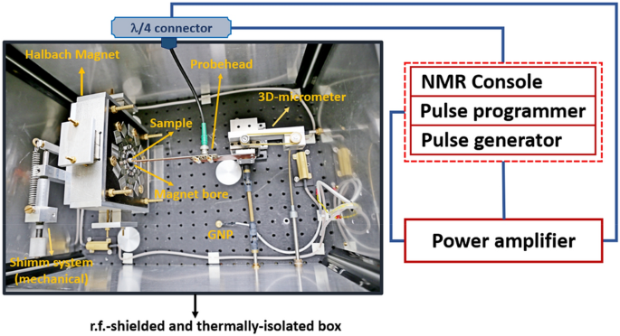
The homebuilt LF-NMR system geared up with an MLHB magnet, labeled with its elements: NMR probe-head, floor coupling (GND), multilayer Halbach magnet (MLHB), mechanical shim system, 3D-stage micrometer, thermally remoted and r.f.-shielded field, NMR console (pulse programmer and pulse generator), and energy amplifier.
The magnet used reveals a ({mathrm{B}}_{0}) homogeneity of ({Delta mathrm{B}}_{0}/{mathrm{B}}_{0}={10}^{-4}) inside a cylindrical free quantity measuring 2.4 mm in diameter and three mm in size (coil size), which is bigger than the meant pattern dimension to forestall linewidth broadening. The NMR probe-head was mounted on a high-precision 3-axis stage micrometer to find the magnet’s candy spot for conducting NMR measurements. Moreover, a high-precision rotation stage, adjustable in 1° increments (Thorlabs Inc.), was employed to rotate the complete magnet relative to the probe-head, enhancing the alignment (({mathrm{B}}_{0}) perpendicular to ({mathrm{B}}_{1})) between the magnet and the probehead. This alignment enchancment contributed experimentally to reaching narrower linewidth. The temperature management system for each the magnet and the NMR probe was housed in a homebuilt r.f. shielded field made of two mm thick aluminum. The field was thermally insulated utilizing a formfitting polyurethane foam jacket and geared up with a heating system. Temperature regulation was achieved by means of a standalone programmable business temperature controller, and passive vibration isolation measures have been carried out to suppress mechanical vibrations.
Amplitude-modulated pulses have been generated utilizing a Radio Processor board (SpinCore Applied sciences, Inc., Gainesville, FL, USA). Determine 11 presents a 3D plot illustrating the measured NMR sign amplitude variations in response to modifications within the energy of 90° pulses (with a hard and fast pulse length optimized individually at 1.9 ms) and the central resonance frequency (O1) of ({mathrm{B}}_{0}). The evaluation aimed to find out the parameters for efficient and optimized NMR measurements, revealing {that a} energy vary of 1.9–2.5 W and a central resonance frequency inside ± 5 Hz yielded optimum outcomes, with solely a 7% lower in amplitude even at off-resonance frequencies inside this vary.
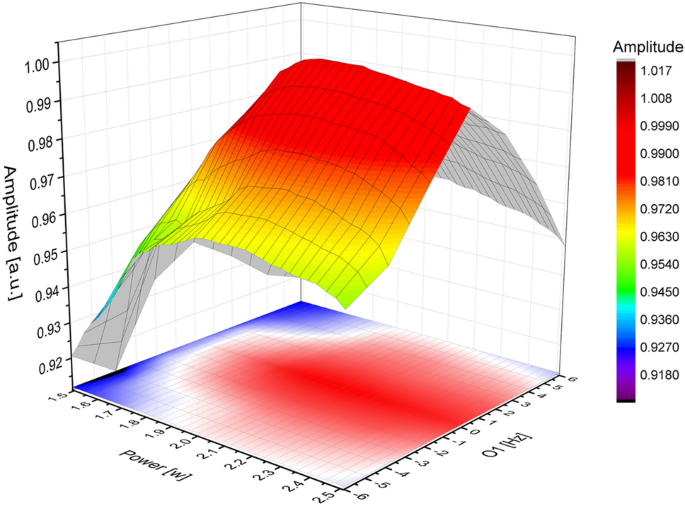
A 3D plot illustrating the variations in NMR sign amplitude as a perform of B1 energy (energy of the 90° laborious pulse) and central resonance frequency (O1) of ({mathrm{B}}_{0}).